- Index
-
Categories
- integrated circuit 0 Items
- Discrete Semiconductors 0 Items
-
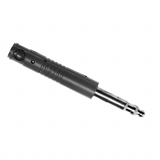
Connectors, Interconnects
3,773,546 Items
- Circular Connectors 1,406,863 Items
- Rectangular Connectors 1,109,431 Items
- Card Edge Connectors 643,773 Items
- Terminal Blocks 201,396 Items
- D-Sub, D-Shaped Connectors 132,630 Items
- Backplane Connectors 56,004 Items
- Coaxial Connectors (RF) 39,118 Items
- Terminals 38,960 Items
- Modular Connectors 28,200 Items
- Sockets for ICs, Transistors 23,858 Items
- Heavy Duty Connectors 21,586 Items
- FFC, FPC (Flat Flexible) Connectors 16,374 Items
- AC Power Connectors 11,487 Items
- Fiber Optic Connectors 5,970 Items
- Pluggable Connectors 5,652 Items
-
- View All
- Resistors 1,464,842 Items
-
Capacitors
1,233,524 Items
- Ceramic Capacitors 802,073 Items
- Film Capacitors 165,215 Items
- Aluminum Electrolytic Capacitors 119,232 Items
- Tantalum Capacitors 106,098 Items
- Tantalum - Polymer Capacitors 12,401 Items
- Mica and PTFE Capacitors 9,477 Items
- Aluminum - Polymer Capacitors 8,499 Items
- Thin Film Capacitors 3,401 Items
- Electric Double Layer Capacitors (EDLC),... 2,508 Items
- Capacitor Networks, Arrays 2,073 Items
- Trimmers, Variable Capacitors 1,755 Items
- Silicon Capacitors 317 Items
- Accessories 256 Items
- Niobium Oxide Capacitors 219 Items
-
- View All
-
Crystals, Oscillators, Resonators
755,151 Items
- Oscillators 612,879 Items
- Crystals 121,233 Items
- Programmable Oscillators 10,110 Items
- Pin Configurable/Selectable Oscillators 8,173 Items
- Resonators 1,894 Items
- VCOs (Voltage Controlled Oscillators) 669 Items
- Crystal, Oscillator, Resonator Accessori... 168 Items
- Stand Alone Programmers 25 Items
-
- View All
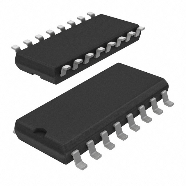
- Integrated Circuits (ICs) 656,537 Items
-
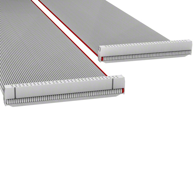
Cable Assemblies
484,842 Items
- Rectangular Cable Assemblies 151,241 Items
- Coaxial Cables (RF) 93,552 Items
- Circular Cable Assemblies 83,895 Items
- Modular Cables 40,571 Items
- Fiber Optic Cables 31,336 Items
- Jumper Wires, Pre-Crimped Leads 22,945 Items
- Flat Flex Ribbon Jumpers, Cables 20,760 Items
- Pluggable Cables 11,415 Items
- D-Sub Cables 7,601 Items
- Between Series Adapter Cables 4,775 Items
- USB Cables 4,234 Items
- Power, Line Cables and Extension Cords 4,151 Items
- Flat Flex Jumpers, Cables (FFC, FPC) 2,015 Items
- Video Cables (DVI, HDMI) 1,713 Items
- Specialized Cable Assemblies 1,689 Items
-
- View All
-
Switches
421,703 Items
- Pushbutton Switches 176,200 Items
- Rocker Switches 51,872 Items
- Toggle Switches 33,225 Items
- Limit Switches 23,445 Items
- Selector Switches 23,261 Items
- Configurable Switch Components 21,862 Items
- Keylock Switches 16,724 Items
- Accessories 16,721 Items
- Rotary Switches 13,933 Items
- Tactile Switches 13,531 Items
- DIP Switches 8,271 Items
- Accessories - Caps 4,679 Items
- Slide Switches 4,310 Items
- Interlock Switches 3,299 Items
- Emergency Stop (E-Stop) Switches 2,802 Items
-
- View All
-
Hardware, Fasteners, Accessories
318,542 Items
- Board Spacers, Standoffs 209,589 Items
- Screws, Bolts 23,641 Items
- Structural, Motion Hardware 21,916 Items
- Springs 15,272 Items
- Knobs 7,652 Items
- Seals - O-Rings 7,457 Items
- Bumpers, Feet, Pads, Grips 6,967 Items
- Miscellaneous 4,427 Items
- Washers 3,959 Items
- Accessories 3,263 Items
- Board Supports 2,987 Items
- Hole Plugs - Tapered Caps 2,238 Items
- Reclosable Fasteners 1,579 Items
- Rivets 1,520 Items
- Nuts 1,415 Items
-
- View All
-
Circuit Protection
306,645 Items
- Circuit Breakers 115,397 Items
- Transient Voltage Suppressors (TVS) 109,917 Items
- Fuses 23,615 Items
- Electrical, Specialty Fuses 18,762 Items
- Varistors, MOVs 15,992 Items
- Fuseholders 6,012 Items
- Circuit Protection Accessories 5,100 Items
- PTC Resettable Fuses 5,024 Items
- Gas Discharge Tube Arresters (GDT) 3,698 Items
- Inrush Current Limiters (ICL) 1,291 Items
- Ground Fault Circuit Interrupter (GFCI) 811 Items
- Surge Suppression Ics 535 Items
- Thermal Cutoffs (Thermal Fuses) 413 Items
- Lighting Protection 78 Items
-
- View All
- Power Supplies - Board Mount 257,357 Items
- Discrete Semiconductor Products 252,065 Items
-
Power Supplies - External/Internal (Off-...
236,527 Items
- AC DC Converters 198,098 Items
- AC DC Desktop, Wall Power Adapters 13,328 Items
- DC DC Converters 12,420 Items
- LED Drivers 5,076 Items
- Industrial, DIN Rail Power Supplies 4,230 Items
- External/Internal Power Supply Accessori... 1,823 Items
- Power over Ethernet (PoE) 733 Items
- AC DC Configurable Power Supplies (Facto... 317 Items
- AC DC Configurable Power Supply Chassis 208 Items
- AC AC Wall Power Adapters 172 Items
- AC DC Configurable Power Supply Modules 122 Items
-
- View All
-
Optoelectronics
190,705 Items
- LED White Lighting 35,601 Items
- LED COBs, Engines, Modules, Strips 31,944 Items
- LED Indication - Discrete 22,927 Items
- Panel Indicators, Pilot Lights 20,243 Items
- Fiber Optic Transceiver Modules 16,349 Items
- Light Pipes 15,198 Items
- Circuit Board Indicators, Arrays, Light... 7,489 Items
- Optoelectronics Accessories 6,346 Items
- LED Color Lighting 4,391 Items
- LED Character and Numeric 4,347 Items
- LCD, OLED, Graphic 4,233 Items
- LED Emitters - Infrared, UV, Visible 3,590 Items
- Lenses 3,385 Items
- Spacers, Standoffs 2,700 Items
- LCD, OLED Character and Numeric 1,966 Items
-
- View All
-
Sensors, Transducers
174,312 Items
- Pressure Sensors, Transducers - Industri... 26,266 Items
- Optical Sensors 26,224 Items
- Temperature Sensors 23,787 Items
- Encoders 12,059 Items
- Proximity Sensors - Industrial 11,700 Items
- Magnetic Sensors 9,862 Items
- Pressure Sensors, Transducers 9,028 Items
- Sensor, Transducer Accessories 8,329 Items
- Encoders - Industrial 4,791 Items
- Position Sensors 4,549 Items
- Proximity Sensors 4,282 Items
- Current Sensors 3,582 Items
- Motion Sensors 3,379 Items
- Sensor Cable Assemblies 3,180 Items
- Sensor Cable Accessories 3,098 Items
-
- View All
- Inductors, Coils, Chokes 160,301 Items
-
- View All
-
Manufacturers
- Samtec, Inc. 987,039 Items
- EDAC Inc. 525,451 Items
-
Vishay / Dale
424,741 Items
- Uncategorized 2 Items
- Resistors 414,808 Items
- Capacitors 5 Items
- Inductors, Coils, Chokes 7,324 Items
- Optoelectronics 341 Items
- Transformers 22 Items
- Crystals, Oscillators, Resonators 8 Items
- Motors, Actuators, Solenoids and Drivers 6 Items
- Discrete Semiconductor Products 1 Items
- Connectors, Interconnects 1,181 Items
- Sensors, Transducers 905 Items
- Kits 15 Items
- Development Boards, Kits, Programmers 9 Items
- Filters 114 Items
-
- View All
-
TOKIN (KEMET)
303,689 Items
- Uncategorized 1,201 Items
- Resistors 2 Items
- Capacitors 296,947 Items
- Inductors, Coils, Chokes 1,340 Items
- Circuit Protection 294 Items
- Audio Products 1 Items
- Transformers 17 Items
- Motors, Actuators, Solenoids and Drivers 71 Items
- Relays 318 Items
- Connectors, Interconnects 37 Items
- Cable Assemblies 1 Items
- Sensors, Transducers 530 Items
- Kits 138 Items
- Development Boards, Kits, Programmers 22 Items
- Filters 2,386 Items
-
- View All
- Knowles Syfer 281,575 Items
- KOA Speer Electronics, Inc. 269,115 Items
- Amphenol Aerospace Operations 266,006 Items
- RAF 222,627 Items
- YAGEO 217,807 Items
- Sullins Connector Solutions 203,250 Items
- SiTime 190,477 Items
-
Vicor
180,804 Items
- Uncategorized 21 Items
- Capacitors 9 Items
- Inductors, Coils, Chokes 18 Items
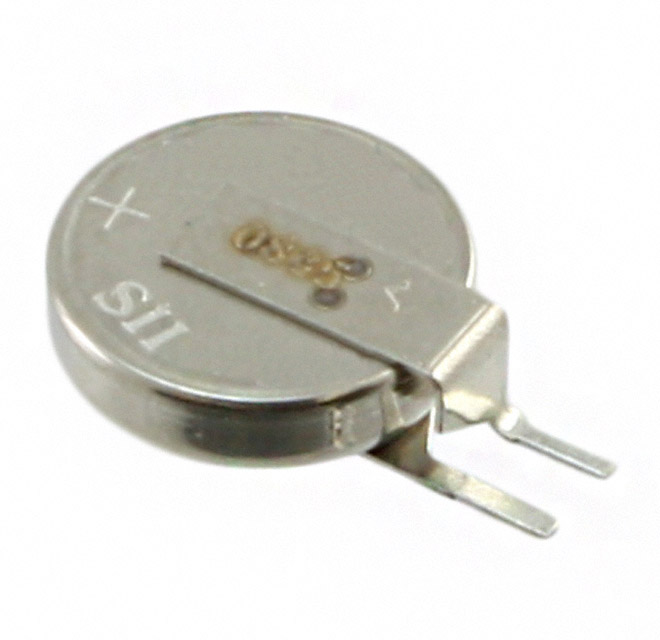
- Battery Products 2 Items
- Power Supplies - External/Internal (Off-... 3,048 Items
- Circuit Protection 9 Items
- Fans, Blowers, Thermal Management 20 Items
- Discrete Semiconductor Products 3 Items
- Connectors, Interconnects 1 Items
- Sensors, Transducers 1 Items
- Hardware, Fasteners, Accessories 38 Items
- Kits 10 Items
- Integrated Circuits (ICs) 77 Items
- Development Boards, Kits, Programmers 314 Items
- Filters 9 Items
-
- View All
-
Roving Networks (Microchip Technolog...
150,984 Items
- Uncategorized 54 Items
- Resistors 1 Items
- Capacitors 22 Items
- Inductors, Coils, Chokes 1 Items
- Optoelectronics 4 Items
- Power Supplies - External/Internal (Off-... 232 Items
- Circuit Protection 21,678 Items
- Crystals, Oscillators, Resonators 18,757 Items
- Relays 156 Items
- Fans, Blowers, Thermal Management 1 Items
- Tools 1 Items
- Discrete Semiconductor Products 40,597 Items
- Cable Assemblies 8 Items
- Memory - Modules, Cards 9 Items
- Sensors, Transducers 685 Items
-
- View All
-
SCHURTER
138,147 Items
- Uncategorized 1 Items
- Inductors, Coils, Chokes 79 Items
- Optoelectronics 93 Items
- Power Supplies - External/Internal (Off-... 1 Items
- Circuit Protection 25,074 Items
- Transformers 47 Items
- Switches 107,839 Items
- Tools 1 Items
- Connectors, Interconnects 3,474 Items
- Cable Assemblies 155 Items
- Sensors, Transducers 1 Items
- Hardware, Fasteners, Accessories 76 Items
- Test and Measurement 17 Items
- Kits 40 Items
- Development Boards, Kits, Programmers 6 Items
-
- View All
-
KYOCERA AVX
123,880 Items
- Uncategorized 26 Items
- Resistors 332 Items
- Capacitors 109,771 Items
- Inductors, Coils, Chokes 634 Items
- Potentiometers, Variable Resistors 52 Items
- Optoelectronics 3 Items
- Circuit Protection 1,048 Items
- Audio Products 34 Items
- Crystals, Oscillators, Resonators 2,189 Items
- Switches 5 Items
- Fans, Blowers, Thermal Management 111 Items
- Tools 61 Items
- Discrete Semiconductor Products 288 Items
- Connectors, Interconnects 7,155 Items
- Cable Assemblies 6 Items
-
- View All
-
- View All
- News
- Solution
- ABOUT US
- Contact US